PNEUMATICS
Pneumatic logic can be divided into three parts
1. Supply Components - This is for the end user side application and for Logic sequence.
These components include - Compressors , Air filters , Water separators, Lubricaors and Air dryers
2. Logic components : These form the intermediary conditional elements to achieve the required end action. These elements also encompass Feed back loop for proper process control.
Components include: Direction control valves with pneumatic/ electrical actuation , Logic elements ,
3.End Components : These are the user end side components incorporated in machinery to perform the necessary action in an automation system.
These include Rams , Motors. - Basically called as Actuators and Drives
Supply Components


Cleanliness is important in pneumatic system , as water vapour and dirt can clog the logical components , restrict their function and also corrode the casings of aluminium die cast components.Hence supply of de-humidified air is imporatnt with water removal by dryers/ dessicant systems , along with line water separators. Lubricators are provoded to ensure proper functioning of logical components.
Logic components
These can be divided into following :
1.Direction control valves : These valves change the direction of supply based on the actuation logic. These are designated as Number of ports/ Number of ways Valve (Ex: 5/2 valve - 5 ports / 2 way valve). and the condition is designated as Normally open (NO) and Normally closed (NC) , based on the logic- control air passing through(NO) or control air not passing through(NC).
The ports are designated and standardized as described below.


2.Actuation methods
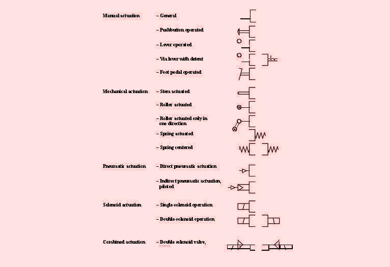
Direct actuation · Simplest
possibility
· Input element = Control
element
Indirect actuation · Usual
type of actuation
· For cylinders with large
diameters
· In case of large distance
between input element and working element


4.Pressure control system includes pressure regulating valves , pressure sequence valves.
Variable controls are indicated by slant lines on the valve notations.


End components


Representation of a Pneumatic logic with numbering
System
number
|
1,2 etc | |||
· Is used only if the entire switching
circuit consists of more than one system
|
||||
Circuit
number
|
·
|
Components of
energy supply, accessories
|
0
|
|
·
|
Fluid
circuits; Number assignment per cylinder
|
1, 2, ...
|
||
Component
designation
|
by letter
|
|||
·
|
Working elements
|
A ( End components)
|
||
·
|
Compressors
|
P
|
||
·
|
Sensors
|
S ( Actuators or valves controlled by logic)
|
||
·
|
Valves
|
V
|
||
·
|
Other components
|
Z
|
||
Component
number
|
·
|
Beginning with 1
|
||
· Continuous numbering of the
same types of component
Numbers assigned from left to
right and from bottom to top
Direct actuation · Simplest
possibility
· Input element = Control
element
Indirect actuation · Usual
type of actuation
· For cylinders with large
diameters
· In case of large distance
between input element and working element
A simple circuit is explained as under

signal is present at
both inputs of the dual pressure valve 1V1 by 1 S1 and 1 S2, the control element 1V3 switches and the
piston rod of cylinder 1A moves forward till it reaches end point 1S3.
1S3 sends delay signal to port 12 of time delay valve 1V2 , which switches control when time delay is elapsed , thus changing position on valve 1V3 - to return back to original position.
The possibilities are endless , as the logic remains the same so as the elements , but time delay sequences can also be enacted by electro- pneumatic valves (pneumatic valves activated by solenoids) .
.
Your article is well discovered upon the pneumatic, I am Clayton Kennelly a skilled pneumatic operator. I found it very useful as it got explained that Pneumatic logic in three parts - Supply Components, Logic components, and End Components. Moreover, it well described very well individually.
ReplyDeleteNice Blog, Shree Techno Engineers is the top best manufacturer and supplier of Coal Handling System, Ash Handling System and Rotary Airlock Valve Manufacturer in India.
ReplyDelete