Welding as a method of joining two or more pieces of metal together is a universal technique. In every manufacturing industry, be it small or large, welding has its place.
The quality of a weld depends on a number of factors
-Choice of design
-Consumables
-Welding process
The presence of discontinuities in welding has been accepted as inevitable, the problem arises of defining what is acceptable. It is often difficult to establish exactly what size and type of discontinuity is present. Before any judgement of acceptability is made regarding the scope of job and the corrective measures- the aspects need to be considered are the quality of the weld, in terms of size, type, location and frequency of discontinuities.

1. Crack or crack like Discontinuities
Cracklike fabrication defects normally result from unsuitable materials and/or welding procedure; and are intensified if combined with poor workmanship. Solidification cracking is caused by high thermally induced strain acting on insufficiently ductile weld metal.


Such discontinuities may arise from inadequate design and/or fabrication but some are inherent in the welding process, and this should always be taken into consideration. To make a weld totally free of any discontinuity if impossible.


- Hydrogen cracking can occur in the heat affected zone (HAZ) or weld metal, the former being the more common. It is caused by hydrogen diffusion from contaminated weld metal which embrittles the microstructure to such an extent that only a low level of strain results in fracture.
-Low hydrogen electrodes and submerged arc fluxes have been developed to combat hydrogen cracking, but possibly the most common cause is the usage of damp electrodes or fluxes.
Proper control of environmental parameters such as water retention of electrode flux bybaking electrodes and proper inter-pass temperature as shown in the graph can help diffuse hydrogen and thus eliminate cracks.

-Lamellar tearing is a form of cracking associated with the presence of planes of non-metallic inclusions in the parent plate which reduce the transverse ductility to a level insufficient to accommodate thermally induced strain. This problem is most prevalent in heavy sections or highly restrained joints and can be avoided ei ther by careful joint design, or preferably by using better quality steel.The tendency of crack propagation is due to formation of stress post cooling in perpendicular to induced stress pattern , due to differential alloying in HAZ and thus results in Banding -by way of different microstructures between alloyed concentrations - this can increase the induced stress on the banded zones thus cause cracking.(microstructural changes - resulting in additional stresses over the induced ones).This results in a crack formation in HAZ zone - excluding the weld itself and below the weld- leading to a through/through damage .Thus Lamellar cracks propagate through weaker structures or bands excluding stronger zones .
T-section shrinkage is as illustrated.


In general, cracks or cracklike discontinuities are a result of incorrect or inadequate selection of
materials, consumables, or procedure, and are sometimes beyond the control of the welder. This has important ramifications where inspection and quality control are concerned, as will be explained later.
Cracks are the most common type of service induced discontinuity. It has been estimated that 90% of all structural failures result directly from fatigue cracking, or brittle fracture following on fatigue cracking.
Both types of failure normally initiate from a fabrication induced discontinuity, but not necessarily one that was cracklike.
Stress corrosion cracking is an environmentally produced cracklike discontinuity which, as the name implies, is a product of corrosion acting on stressed metal.
2. Geometric Discontinuities
A geometric discontinuity in this context is a sudden change of shape or a surface irregularity. Weld profile is usually considered as a geometric discontinuity, although most are inherent in the design, for example, sudden changes of section at a weld joint, or the provision of a permanent backing bar beneath a single sided butt weld.
Misalignment is a common source of geometric discontinuity not directly associated with the weld, as is angular distortion.
The weld profile discontinuities in particular can be classified under the following headings:
a.Undercut.
b. Concavity or convexity.
c. Excessive (or insufficient) reinforcement
d. poor reinforcement angle.
e. Overlap.
f. Burn-through.
h. Shrinkage.
i. Surface irregularity.

All the above are directly within the control of the welder, and are consequently favoured areas of inspection where workmanship is under examination. Also under the control of the welder, but not directly associated with the weld are stray arc strikes and weld spatter.
Service induced geometric discontinuities are rare, the only likely one being pitting as a result of corrosion attack.
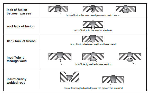
3 Lack of Fusion and Lack of Penetration
 PARAMETERS INFLUENCING LACK OF FUSION


These discontinuities have heen placed in their own category, for although they are usually planar, they differ from cracks in that their extremities are relatively blunt. They are indications of incorrect welding procedure, poor workmanship, poor joint design,or a comhination of these.
Lack of penetration can be deliberate, as in a partial penetration butt weld. Lack of side-wall fusion can be through-thickness, especially in single pass weld. Lack of inter-run fusion is a phenonemon associated with multi-pass welds, and is usually no more than one weld run deep at any particular location.
4.Slag Inclusion

Buried slag inclusions occur predominantly in multiple-pass welds, and may be intermittent or continuous. This type of discontinuity is largely process controlled, and is influenced particularly by choice of flux/electrode and weld geometry.

A well-rounded weld bead in a deep narrow preparation is much more likely to trap slag along the weld toes than a flatter weld bead in a more open joint. The presence of buried slag is often indicative or poor workmanship, because although the formation is a function of process and consumables, most slag should normally be removed by the operator before the next weld pass is made.
5.Porosity
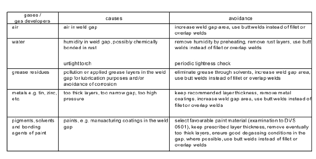


Porosity is usually spherical, or"worm-hole" which is essentially tubular. It may be scattered or clustered, and buried or surface breaking. It results from gas in the molten weld metal failing to escape completely to the surface. The formation of the gas usually arises due to the presence of contaminants on either the consumable or the metal surfaces, and also from failure of shielding gas (GMA processes) or loss of flux (submerged arc or SMA processes). As such, it is a result of inadequate cleanliness and is indicative of poor weld procedure or workmanship. Like slag, porosity levels are often used as a guide to the standard of workmanship achieved. It is interesting to examine the effect of welding process alone on the preponderance of the various types of defect.
Methods of Detecting Weld Discontinuities
NDT the most Common ones being:
1. Visual inspection.
2. Dye penetrant.
3. Magnetic particle.
4. Radiography.
5.Ultrasonic testing.
Visual Inspection: Visual inspection is by far the most commonly used method of NDT. It is the most appropriate method of checking for weld profile and geometric discontinuities, although its accuracy and repeatability can vary considerably. One factor which affects this is the skill and training of the individual inspector. Other factors include access, lighting, and surface condition of the material.
Aids to visual inspection which most inspectors use include a portable light source, a small mirror, weld profile gauge, and a low power magnifying glass. These make the detection of quite small surface discontinuities possible.
Geometric discontinuities, surface breaking porosity can be found, but surface breaking cracks will not often be visually detectable. Where single sided butt joints are made, the root surface will not always be accessible, and obviously, buried discontinuities cannot be detected visually.
Dye Penetrant and Magnetic Particle :These methods of NDT are limited to detecting cracklike surface breaking discontinuities.They can be considered as an extension to visual inspection, since they enhance the appearance of the above type of discontinuity so that they become visible to the naked eye, whereas they may not have been visible normally.
Radiography : Voids such as porosity, and non-metallic inclusions such as slag are more transparent to the radiation than solid metal, and thus a radiation path containing such discontinuities has less attenuation and produces a stronger image on the film. To be successful, this technique requires good control of exposure and development of the film. Access to both sides of the joint is desirable, but in relatively simple joints such as a pipe girth weld, the technique can be just as effective when the exposure is made through both walls when access to the inside is not possible. On more complicated joints,it becomes increasingly difficult to obtain a satisfactory exposure of the weld in question without undue interference from other material. This is especially true of fillet welds. The method is good for detection of buried volumetric discontinuities, such as slag and porosity.
It can indicate geometric discontinuities such as "waggon track" root concavity in pipe welds. However it is unlikely to detect crack-like discontinuities, unless the planes these happen to lie within a few degrees of parallel to the beam direction. The length of the discontinuity is easily determined, but the thickness in the depth direction is almost impossible to estimate, although an experienced operator may be prepared to pass judgement based on the relative densities of the radiographic
Ultrasonic Testing :
Ultrasonic testing relies on the principle that the propagation of sound waves through a nominally homogeneous material is altered by discontinuities within the material. Surface boundaries, both external and internal (as present at cracks, Lack of Fusion and Lack Of Penetration,slag and porosity), act as reflectors to the ultrasound, and detection of these reflections indicates the presence of a discontinuity. However, surface effects and metallurgical conditions such as coarse grain boundaries can also produce signals which may be erroneously interpreted. The effectiveness of ultrasonic testing compared with radiography depends on many factors.
Ultrasonics becomes progressively more effective with increasing thickness, except where clusters of porosity are concerned . It is much more successful at detecting planar discontinuities such as cracks, Lack Of Fusion and Lack Of Penetration. It can locate the position and depth of a discontinuity, as well as its length.Ultrasonic methods have the potential to reveal much more information about the discontinuity.Unlike radiography, ultrasonic testing does not normally provide a hard copy of results, so all decisions will normally have to be made by the operator on site.
Acceptance standards of welds
-Maximum convexity for fillet welds :0.07 x face width plus 1.5mm maximum
-Overfill for full penetration butt welds :3.2mm maximum
-Limits on depth of undercut vary between 0.25mm and 1.6mm, and depend on a rather complex and arbitrary relationship between proportional length, direction of principal stress (longitudinal or transverse with respect to weld), and thickness
- Cracks and lack of fusion are universally unacceptable.
-Piping porosity limitations are based on diameter and frequency in an equally complex and confusing fashion.
- Radiography defines limits based on maximum diameter of indication in association with weld size.
Ultrasonic inspection is based on four severity levels, and is defined by signal amplitude measurement. For tubular joints, assessment is very complex.
The quality of a weld depends on a number of factors
-Choice of design
-Consumables
-Welding process
The presence of discontinuities in welding has been accepted as inevitable, the problem arises of defining what is acceptable. It is often difficult to establish exactly what size and type of discontinuity is present. Before any judgement of acceptability is made regarding the scope of job and the corrective measures- the aspects need to be considered are the quality of the weld, in terms of size, type, location and frequency of discontinuities.

1. Crack or crack like Discontinuities
Cracklike fabrication defects normally result from unsuitable materials and/or welding procedure; and are intensified if combined with poor workmanship. Solidification cracking is caused by high thermally induced strain acting on insufficiently ductile weld metal.

 |
| solidification crack |


 |
| COLD CRACKING FACTORS |
Such discontinuities may arise from inadequate design and/or fabrication but some are inherent in the welding process, and this should always be taken into consideration. To make a weld totally free of any discontinuity if impossible.


- Hydrogen cracking can occur in the heat affected zone (HAZ) or weld metal, the former being the more common. It is caused by hydrogen diffusion from contaminated weld metal which embrittles the microstructure to such an extent that only a low level of strain results in fracture.
-Low hydrogen electrodes and submerged arc fluxes have been developed to combat hydrogen cracking, but possibly the most common cause is the usage of damp electrodes or fluxes.
Proper control of environmental parameters such as water retention of electrode flux bybaking electrodes and proper inter-pass temperature as shown in the graph can help diffuse hydrogen and thus eliminate cracks.

-Lamellar tearing is a form of cracking associated with the presence of planes of non-metallic inclusions in the parent plate which reduce the transverse ductility to a level insufficient to accommodate thermally induced strain. This problem is most prevalent in heavy sections or highly restrained joints and can be avoided ei ther by careful joint design, or preferably by using better quality steel.The tendency of crack propagation is due to formation of stress post cooling in perpendicular to induced stress pattern , due to differential alloying in HAZ and thus results in Banding -by way of different microstructures between alloyed concentrations - this can increase the induced stress on the banded zones thus cause cracking.(microstructural changes - resulting in additional stresses over the induced ones).This results in a crack formation in HAZ zone - excluding the weld itself and below the weld- leading to a through/through damage .Thus Lamellar cracks propagate through weaker structures or bands excluding stronger zones .
T-section shrinkage is as illustrated.


Underclad cracks occur during stress relief heat treatment of welds, occurring close to a coarser grain zone near fusion line.This occurs during post weld heat treatment of cladded materials.

In general, cracks or cracklike discontinuities are a result of incorrect or inadequate selection of
materials, consumables, or procedure, and are sometimes beyond the control of the welder. This has important ramifications where inspection and quality control are concerned, as will be explained later.
Cracks are the most common type of service induced discontinuity. It has been estimated that 90% of all structural failures result directly from fatigue cracking, or brittle fracture following on fatigue cracking.
Both types of failure normally initiate from a fabrication induced discontinuity, but not necessarily one that was cracklike.
Stress corrosion cracking is an environmentally produced cracklike discontinuity which, as the name implies, is a product of corrosion acting on stressed metal.
2. Geometric Discontinuities
A geometric discontinuity in this context is a sudden change of shape or a surface irregularity. Weld profile is usually considered as a geometric discontinuity, although most are inherent in the design, for example, sudden changes of section at a weld joint, or the provision of a permanent backing bar beneath a single sided butt weld.
Misalignment is a common source of geometric discontinuity not directly associated with the weld, as is angular distortion.
The weld profile discontinuities in particular can be classified under the following headings:
a.Undercut.
b. Concavity or convexity.
c. Excessive (or insufficient) reinforcement
d. poor reinforcement angle.
e. Overlap.
f. Burn-through.
h. Shrinkage.
i. Surface irregularity.

All the above are directly within the control of the welder, and are consequently favoured areas of inspection where workmanship is under examination. Also under the control of the welder, but not directly associated with the weld are stray arc strikes and weld spatter.
Service induced geometric discontinuities are rare, the only likely one being pitting as a result of corrosion attack.
3 Lack of Fusion and Lack of Penetration


These discontinuities have heen placed in their own category, for although they are usually planar, they differ from cracks in that their extremities are relatively blunt. They are indications of incorrect welding procedure, poor workmanship, poor joint design,or a comhination of these.
Lack of penetration can be deliberate, as in a partial penetration butt weld. Lack of side-wall fusion can be through-thickness, especially in single pass weld. Lack of inter-run fusion is a phenonemon associated with multi-pass welds, and is usually no more than one weld run deep at any particular location.
4.Slag Inclusion

Buried slag inclusions occur predominantly in multiple-pass welds, and may be intermittent or continuous. This type of discontinuity is largely process controlled, and is influenced particularly by choice of flux/electrode and weld geometry.

A well-rounded weld bead in a deep narrow preparation is much more likely to trap slag along the weld toes than a flatter weld bead in a more open joint. The presence of buried slag is often indicative or poor workmanship, because although the formation is a function of process and consumables, most slag should normally be removed by the operator before the next weld pass is made.
5.Porosity


Porosity is usually spherical, or"worm-hole" which is essentially tubular. It may be scattered or clustered, and buried or surface breaking. It results from gas in the molten weld metal failing to escape completely to the surface. The formation of the gas usually arises due to the presence of contaminants on either the consumable or the metal surfaces, and also from failure of shielding gas (GMA processes) or loss of flux (submerged arc or SMA processes). As such, it is a result of inadequate cleanliness and is indicative of poor weld procedure or workmanship. Like slag, porosity levels are often used as a guide to the standard of workmanship achieved. It is interesting to examine the effect of welding process alone on the preponderance of the various types of defect.
Methods of Detecting Weld Discontinuities
NDT the most Common ones being:
1. Visual inspection.
2. Dye penetrant.
3. Magnetic particle.
4. Radiography.
5.Ultrasonic testing.
Visual Inspection: Visual inspection is by far the most commonly used method of NDT. It is the most appropriate method of checking for weld profile and geometric discontinuities, although its accuracy and repeatability can vary considerably. One factor which affects this is the skill and training of the individual inspector. Other factors include access, lighting, and surface condition of the material.
Aids to visual inspection which most inspectors use include a portable light source, a small mirror, weld profile gauge, and a low power magnifying glass. These make the detection of quite small surface discontinuities possible.
Geometric discontinuities, surface breaking porosity can be found, but surface breaking cracks will not often be visually detectable. Where single sided butt joints are made, the root surface will not always be accessible, and obviously, buried discontinuities cannot be detected visually.
Dye Penetrant and Magnetic Particle :These methods of NDT are limited to detecting cracklike surface breaking discontinuities.They can be considered as an extension to visual inspection, since they enhance the appearance of the above type of discontinuity so that they become visible to the naked eye, whereas they may not have been visible normally.
Radiography : Voids such as porosity, and non-metallic inclusions such as slag are more transparent to the radiation than solid metal, and thus a radiation path containing such discontinuities has less attenuation and produces a stronger image on the film. To be successful, this technique requires good control of exposure and development of the film. Access to both sides of the joint is desirable, but in relatively simple joints such as a pipe girth weld, the technique can be just as effective when the exposure is made through both walls when access to the inside is not possible. On more complicated joints,it becomes increasingly difficult to obtain a satisfactory exposure of the weld in question without undue interference from other material. This is especially true of fillet welds. The method is good for detection of buried volumetric discontinuities, such as slag and porosity.
It can indicate geometric discontinuities such as "waggon track" root concavity in pipe welds. However it is unlikely to detect crack-like discontinuities, unless the planes these happen to lie within a few degrees of parallel to the beam direction. The length of the discontinuity is easily determined, but the thickness in the depth direction is almost impossible to estimate, although an experienced operator may be prepared to pass judgement based on the relative densities of the radiographic
Ultrasonic Testing :
Ultrasonic testing relies on the principle that the propagation of sound waves through a nominally homogeneous material is altered by discontinuities within the material. Surface boundaries, both external and internal (as present at cracks, Lack of Fusion and Lack Of Penetration,slag and porosity), act as reflectors to the ultrasound, and detection of these reflections indicates the presence of a discontinuity. However, surface effects and metallurgical conditions such as coarse grain boundaries can also produce signals which may be erroneously interpreted. The effectiveness of ultrasonic testing compared with radiography depends on many factors.
Ultrasonics becomes progressively more effective with increasing thickness, except where clusters of porosity are concerned . It is much more successful at detecting planar discontinuities such as cracks, Lack Of Fusion and Lack Of Penetration. It can locate the position and depth of a discontinuity, as well as its length.Ultrasonic methods have the potential to reveal much more information about the discontinuity.Unlike radiography, ultrasonic testing does not normally provide a hard copy of results, so all decisions will normally have to be made by the operator on site.
Acceptance standards of welds
-Maximum convexity for fillet welds :0.07 x face width plus 1.5mm maximum
-Overfill for full penetration butt welds :3.2mm maximum
-Limits on depth of undercut vary between 0.25mm and 1.6mm, and depend on a rather complex and arbitrary relationship between proportional length, direction of principal stress (longitudinal or transverse with respect to weld), and thickness
- Cracks and lack of fusion are universally unacceptable.
-Piping porosity limitations are based on diameter and frequency in an equally complex and confusing fashion.
- Radiography defines limits based on maximum diameter of indication in association with weld size.
Ultrasonic inspection is based on four severity levels, and is defined by signal amplitude measurement. For tubular joints, assessment is very complex.
A valve is a device that regulates, directs or controls the flow of a fluid (gases, liquids, fluidized solids, or slurries) by opening, closing, or partially obstructing various passageways. Valves are technically fittings, but are usually discussed as a separate category.!For more information in regards to visit our website.Thank you! http://www.valvefittingstore.com/
ReplyDeleteMariners Repository: Welding Defects In Service Life Of A Product >>>>> Download Now
Delete>>>>> Download Full
Mariners Repository: Welding Defects In Service Life Of A Product >>>>> Download LINK
>>>>> Download Now
Mariners Repository: Welding Defects In Service Life Of A Product >>>>> Download Full
>>>>> Download LINK pr
Very Nicely explaine the procedure well done.
ReplyDeleteMooring Ropes for Boats
TIG welders make use of different inert gases (although sometimes Argon is enough to do all the work). When working on steel and titanium, using argon would be best. TIG Welders
ReplyDeletePlease share more like that.
ReplyDeletewill help you more:
Our mission is to provide quality lab equipment and the best customer experience possible. We believe that technology can transform the material world when experts lend their skills to joint collaborations.Our experienced team and capabilities allow us to understand your project at a high level and work closely with you to ensure your project’s success. Use our products and get lasting solutions.
Vacuum Valves
Thank you so much for such an informative piece of information :)
ReplyDeleteIf anyone interested similar one's have a look here
best of weldings
Thanks
Nice Blog sir...keep doing good job
ReplyDeleteWelding Repair Solution
ReplyDeletehttps://weldersa.co.za/services/
Get the best welding services near me in Sandton, We offer the professional ARC welding service at affordable price in Sandton. Contact us now - +1 910-626-85255
This is great information about Welding. It will be very helpful who are seeking for best Welding Services.
ReplyDeleteIt is a nice and useful blog that you have posted.It will be very helpful You made some good points there.If you need any type of service you can visit our website.I checked on the web to find out more about the issue and found most people will go along with your views on this website Welding Services in Birmingham
ReplyDeleteWow! Such an informative article. If you are looking for a steel welder in melbourne then Hot and Heavy Welding will be the right choice for you.
ReplyDeleteMariners Repository: Welding Defects In Service Life Of A Product >>>>> Download Now
ReplyDelete>>>>> Download Full
Mariners Repository: Welding Defects In Service Life Of A Product >>>>> Download LINK
>>>>> Download Now
Mariners Repository: Welding Defects In Service Life Of A Product >>>>> Download Full
>>>>> Download LINK 7N
Great information on blog. keep posting more.
ReplyDeletewe sell Thermacut EX-TRAFIRE 45SD in Ludhiana.
great information about Welding Cables.
ReplyDeleteThanks for sharing this blog post with us. Marc Bearings is the leading Spherical Roller Bearings Manufacturer in India.
ReplyDelete